Hydraulic valves are complex components, in which many pipes come together and intersect. The traditional machining method, the cross manifold of the valve is completed by machining cross-drilling. However, due to the limitation of machining angle, fluid efficiency cannot be optimized in the most efficient manner, and it is often necessary to add plugs inside the runner to adjust the flow rate. Meanwhile, the machining process also faces the challenge of co-location accuracy. But with 3D printing technology, hydraulic valves production has been brought into a new level.

The image shows the 90-degree vertical cross structure inside the fluid channel, and the fluid direction has a 90-degree bend. The processing method is through cross-drilling, and there is a terminal plug in the section of the fluid block.

Computer fluid dynamics (CFD) analysis shows that some areas will face the problem of small flow, while some parts will face turbulence. In order to adjust the manifold, a further internal plug is required, but it adds complexity and does not change the situation where the fluid must pass through sharp turns. From the perspective of fluid mechanics, there is a lot of room for improvement in the design of traditionally processed hydraulic manifold blocks.
Selective laser melting additive manufacturing technology, which manufactures products by melting metal powder layer by layer, enables us to optimize the flow path inside the fluid in advance while reducing unnecessary valve body weight.
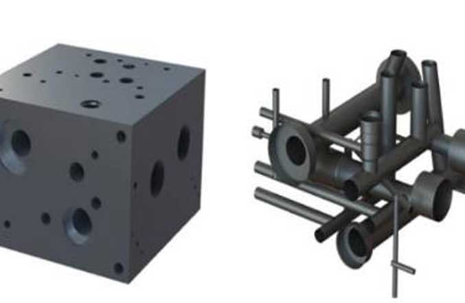
Step 1: Extract the fluid path
The first step is to extract the fluid path, including those cross-drilling designs. This is different from traditional machining which is from a solid metal block. This step requires that the traditional machining fluid does not pass through, but only the holes drilled for processing requirements. This part of design is removed. Leave the pipes through fluid passes, and functional manifolds. The final extracted design is shown on the right.

Step 2: Optimize the manifold
Now, we are beginning to reduce and simplify the fluid flow path. Without the design constraints of cross-drilling, we can replace the sharp corners with a circular curved design to reduce turbulence. The image shows a flow path concept that determines flow separation and stagnation area.

Step 3: Determine the wall thickness and support structure
Once the fluid path is optimized, we need to determine the wall thickness and supporting structure, and use the finite element analysis (FEA) stress model to calculate and analyze the hydrodynamic pressure.

Finally, the support structure acts as a bracket to hold the components together and serves as a construction support and anchor during the construction process. This example shows it not only reduces the weight of the hydraulic valve body by 50%, but also improves the efficiency of fluid flow, avoids the need for further assembly, and improves the performance and stability of the valve body.