Although additive and subtractive manufacturing processes seem to be on quite the opposite ground, in fact, as these technologies develop, the benefits of hybrid manufacturing are increasingly evident. Hybrid manufacturing systems, equipped with additive and subtractive technology simultaneously, could represent a great technological advance for the industry. In this way, these two technologies can be seen as complementary to each other and be able to take advantage of the advantages of each.
1.Hybrid Manufacturing
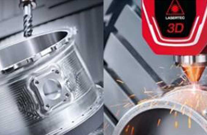
The joint use of additive and subtractive technologies is not a new concept. For example, post-processing of metal parts made by 3D printing often involves CNC machining to give them mechanical precision and a better surface finish. However, there is another way to combine these two processes, resulting in what we call hybrid manufacturing (Figure 1).
Hybrid manufacturing consists of joining an additive and a subtractive technology in the same machine with the aim of taking advantage of the advantages of each of these technologies: the geometric complexity of the additive processes with the high precision of the subtractive processes. In this way, it is possible to obtain an additive and machined part in one step, speeding up the entire production process. Naturally, the design of a hybrid part must take into account the requirements of each of these technologies.
Applications of hybrid systems can be varied as manufacturing small series of metal parts or repairing damaged or worn parts.

Figure 1 - Hybrid fabric (Credit: DMG Mori).
2. Direct Energy Deposition
Direct Energy Deposition (DED) is one of the additive processes that can be used in hybrid technologies. This process consists of fusing the material by a laser or electron beam as it is deposited through a noozle on the construction platform. The deposited material can then be machined to obtain a better surface finish and greater mechanical precision. Alternatively, it is also possible to add material over a machined part to increase the geometric complexity of the part.
Another of the advantages of the DED additive process has to be the fact that it is possible to use a 5-axis system in the print head, enabling the printing of geometrically complex areas without the need to place support structures.
DED is suitable for the production of large parts and repair of mechanical components, and these two characteristics are quite advantageous when we compare this process with laser metal powder melting. On the other hand, the fusion of metallic powder allows obtaining of parts with better finishing and dimensional accuracy.
3. Hybrid Print
It was with the objective of making a hybrid part that we started this project, using a CNC machined part to which we added a castle by the laser metal powder fusion process. We can’t call it hybrid manufacturing, but hybrid printing, since we used two different pieces of equipment, a CNC milling machine and a 3D printer, to make this part.
Another aspect that we wanted to study with this experiment was the bonding capacity between two steels with different chemical compositions. We used a 1.1730 steel construction for the CNC machined part and the hybrid castle was printed with metallic powder of stainless steel 1.4404 (316L).
We will describe below the steps that led to the manufacture of the part shown in figure 2.

Figure 2 - Hybrid part consisting of a CNC machined base and an additive castle.
The project started with the 3D modeling of the part and the study of its attachment to the construction wafer of the 3D printer. We opted for a simple geometry of a parallelepiped with an inner box, to which an additive castle was added, that is, a part that would have to be made using 3D printing. Inside, this castle is made up of a series of thin 1 mm-thick blades (Figure 3) which, despite being a simple geometry, would be very difficult to be executed in any other way.

Figure 3 - Interior section of the hybrid castle.
Another important aspect of this study was how to tighten the hybrid parts to the construction wafer. On the one hand, the printer does not have a parts straightening system, as happens in numerical control machines and, on the other hand, it would be difficult to add a tightening system that would not interfere with the printer’s operating dynamics. Furthermore, the construction wafer is fixed to the printer by four screws, which does not guarantee its performance.
It was decided to make several holes in the wafer thinking about the various possibilities of fixation in future hybrid prints (Figure 4).

Figure 4 - Preparation of the impression wafer.
The construction wafer (and all of its holes) is symmetrical about its central axis. To avoid positioning errors during its tightening on the printer, an arrow indicating its position in relation to the recoater was added, that it, in relation to the mobile mechanism that transports the metallic powder from the feed cylinder onto the construction wafer, such as shown in figure 5.


Figure 5 - Study of the positioning and orientation of the pieces on the construction wafer.
Figure 6 shows us one of the stages of preparation of the construction wafer, namely, the opening of threads with a male.

Figure 6 - Preparation of the construction wafer.

In figure 7 we can see the construction wafer in the 3D printer, covered with metallic powder and ready to start printing the hybrid castle.
Figure 7 - Printer preparation (Printed by Eplus3D EP-M150)
Once the printing is finished, it is necessary to remove the metallic powder that was not cast, as shown in figure 8. Only after removing this powder can we remove the construction wafer from the printer. Unfused powder is sieved and reused for future printing.

Figure 8 - Removal of unfused metal powder (Printed by Eplus3D EP-M150)
After removing all the metallic powder, the construction wafer is removed from the machine and the printing result is shown in figure 9.

Figure 9 - Final result after printing (Printed by Eplus3D EP-M150)
Figure 10 shows three pieces that are the results of this experiment. On the left, we see the base piece without the addition of the hybrid castle. In the middle part, we can see the hybrid bonnet and in the right part, we can see the result after CNC milling the hybrid bonnet. This finishing machining allowed removing the surface roughness left on the exterior walls of the hybrid castle, resulting from the printing process.

Figure 10 - Machined part, machined part with hybrid bonnet, machined part with hybrid bonnet machined by CNC milling.
4. Conclusion
Our first hybrid printing project was successful. We can say that the project had about 70% of preparation and 30% of execution, being the study phase of fixing the pieces to the printing wafer that gave us the most work to define.
Although the laser metal powder melting process is not as versatile as the DED process, we can prove that it is possible to combine CNC milling and laser metal powder melting successfully.
However, it is important to note that we have some limitations here to be taken into account. Hybrid bonnets must grow from a perfectly horizontal and rectified plane to ensure that the bonnets are welded to their base (Figure 11). It would not be possible to carry out this experiment if the printing plane were a surface with a certain three-dimensional profile.

Figure 11 - Print plan indication.
It is also critical to ensure that there are no parts that are above the print plane so that they do not interfere with recoater movement. In other words, if we want to hybrid print a part with more complex geometry, we have to think about how to ensure the connection between parts without interfering with the printer’s dynamics.
It was also possible to demonstrate that it is possible to make a hybrid impression using similar metals, but with different chemical compositions.
Nuno Boavida - Training Technician at the CENFIM Nucleus of Marinha Grande
About Eplus3D Metal 3D Printer EP-M150
EP-M150 adopts metal powder bed selective melting MPBF ™ (Metal Powder Bed Fusion) technology, single and dual-laser printing modes are optional, supporting 200 and 500W laser, which can be perfectly used for the rapid production of high-performance, high-precision parts.
Compatible with most popular metal powder materials, including titanium alloy, aluminum alloy, nickel-based superalloy, Maraging steel, stainless steel, Cobalt, chromium alloy and etc. It has been applied in versatile applications such as industrial manufacturing, medical, education, dental, materials development and etc.

Eplus3D Metal 3D Printer EP-M150